
What is the UL61058 Test for Electrical Switches?
Many professionals working on UL certification for electrical switches are curious about the test requirements for UL61058 certification. JJR Laboratory in China, an independent UL-authorized testing and certification organization, is well-versed in UL standards and certification processes for electrical switches. Below is an introduction to the UL61058 certification test requirements for electrical switches.
Basic Test Requirements for UL61058 Certification
1. Test Samples
- Three samples are required, and they must be tested simultaneously.
2. Adequate Test Circuits
- Some switch designs require two or more test circuits depending on the declared application of the switch.
3. Lab Power System Wiring Diagram
- Includes details about the power source (live/neutral/ground wires), overcurrent protectors, and branches.
4. Lab Layout Diagram
- Should specify the positions of all equipment, such as power sources, overload devices, endurance, temperature rise, and dielectric strength testing devices.
5. Test Circuit Wiring Diagram
- Includes details of the power source (live/neutral/ground wires), the test switch, passive loads, grounding fuses (Dead Metal Fuse), counters, etc.
6. Grounding Fuse (Dead Metal Fuse)
- This fuse is connected to the metallic shell of the switch or its mounting fixture. It must be UL-recognized, with a maximum rated current not exceeding 15A and a minimum voltage equal to or greater than the rated voltage of the switch.
7. Counter
- Counts one cycle every time the test current flows through the switch.
8. Automatic Stop
- The test setup must stop automatically in the event of contact fusion, grounding fuse burnout, or other test failures.
UL61058 Certification Requirements for Power Sources
1. AC Power Requirements
- The “live” and “neutral/ground” sides must be explicitly marked.
2. DC Power Requirements
- The “+” and “-” sides must be clearly marked.
3. Voltage Requirements
- \( V_r \leq V_c \leq 1.05 \, V_r \) (where \( V_c \) is the closed-circuit voltage and \( V_r \) is the rated voltage of the switch).
- \( V_o \leq 1.1 \, V_c \) (where \( V_o \) is the open-circuit voltage).
4. Frequency Requirements
- For switches rated at 50/60 Hz, the test frequency is 50 Hz.
- For switches rated at 60 Hz, the test frequency is 60 Hz.
- For switches rated at 50 Hz, the test frequency is 50 Hz.
5. DC Ripple
- The peak-to-peak ripple voltage must not exceed 5% of the DC voltage.
UL61058 Certification Requirements for Load Side
1. Load Characteristics
- Examples include resistive, inductive, motor loads, or tungsten filament lamps, depending on the declared switch application.
2. AC Load Waveform
- Must be a pure sine wave without distortion or deformation.
3. Inductor Parallel Resistor
- If a hollow inductor is used with a parallel resistor in the circuit, the resistor's power dissipation must not exceed 3% of the total power.
4. Motor Load (EU Regulations)
- Current waveforms must be continuous, with no interruptions. Large waveform durations should last 50-100 ms.
UL61058 Certification Requirements for Test Apparatus
1. Adequate Test Apparatus
- Three samples must be tested simultaneously.
2. Oven Requirement
- For applications exceeding 55°C, an oven must be used, maintaining temperature at \( +0/5°C \) from the set value. Airflow in the oven must not directly impact the test samples.
3. Operation Frequency
- Depending on the current:
- <10A: 15 cycles/min.
- 10A–25A: 7.5 cycles/min.
- >25A: 3.75 cycles/min.
4. ON/OFF Periods per Cycle
- ON: 25% \( (+5/0\%) \), OFF: 75% \( (+5/0\%) \).
- <10A: 1 sec ON, 3 sec OFF.
- 10A–25A: 2 sec ON, 6 sec OFF.
- >25A: 4 sec ON, 12 sec OFF.
5. Speed Requirements
- Mechanical Switches:
- Slow speed: Linear: 20 mm/s; Rotation: ≤45°: 9°/s, >45°: 18°/s.
- Accelerated speed: Linear: 80 mm/s; Rotation: ≤45°: 45°/s, >45°: 90°/s.
- Electronic Switches:
- Accelerated speed: Linear: 25 mm/s; Rotation: 45°/s.
UL61058 Temperature Rise Test Requirements
1. Environment
- Ensure the test area is not affected by wind or thermal conductors to avoid skewing results.
2. Thermocouples
- Preferably Type J; K or T is also acceptable, with wire gauges of 28–32 AWG.
3. Temperature Measuring Instruments
- Channels must be calibrated and specified for use with the designated thermocouple type (J, K, or T).
UL61058 Dielectric Strength Test Requirements
1. Adequate Test Range Validation
- Ensure the equipment covers the necessary range.
2. Test Duration
- The dielectric test must last at least 60 seconds.
The collaboration between telematics and vehicle drive recorders;Benefits of combining drive recorders and telematics;Principles of telematics and drive recorders
Email:hello@jjrlab.com
Write your message here and send it to us
 IECEE CBTL Testing Laboratory for IVD Medical Devi
 China OECD GLP-Certified Laboratory
 Packaging Validation ISO 11607 Test Report
 What is the ISO 11607-1 Packaging Validation Test?
 How to get an ISO 11737-1 Test Report?
 Orthopedic Implant Cleanliness Testing
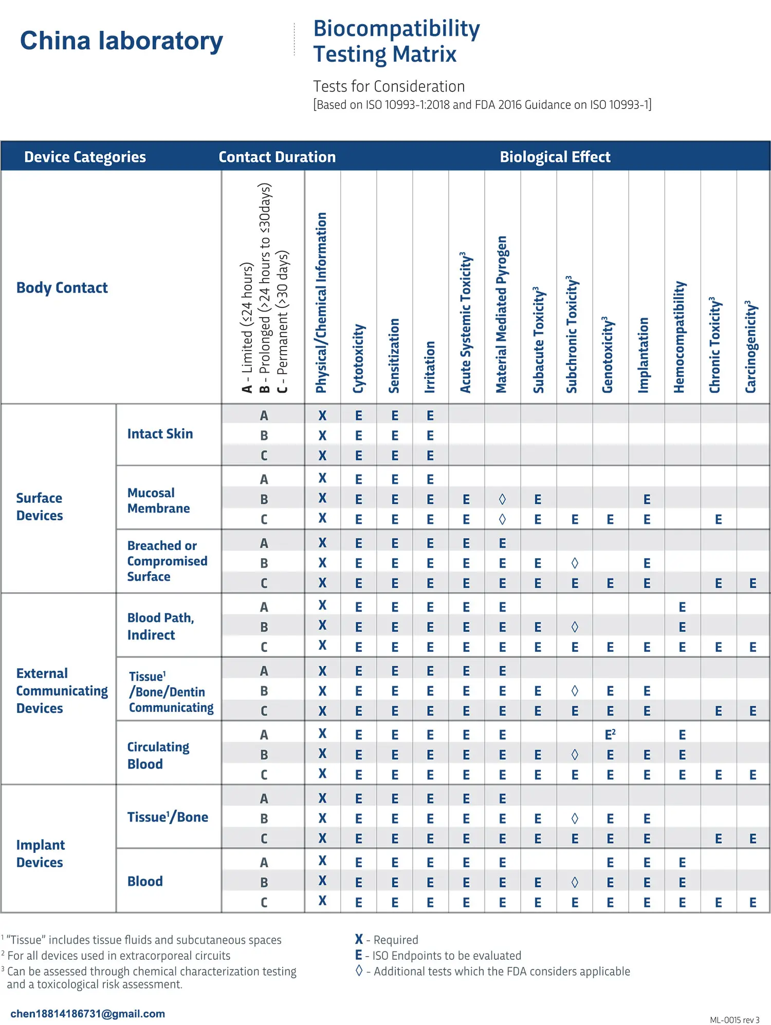 What is ISO 10993-23:2021 Irritation Testing?
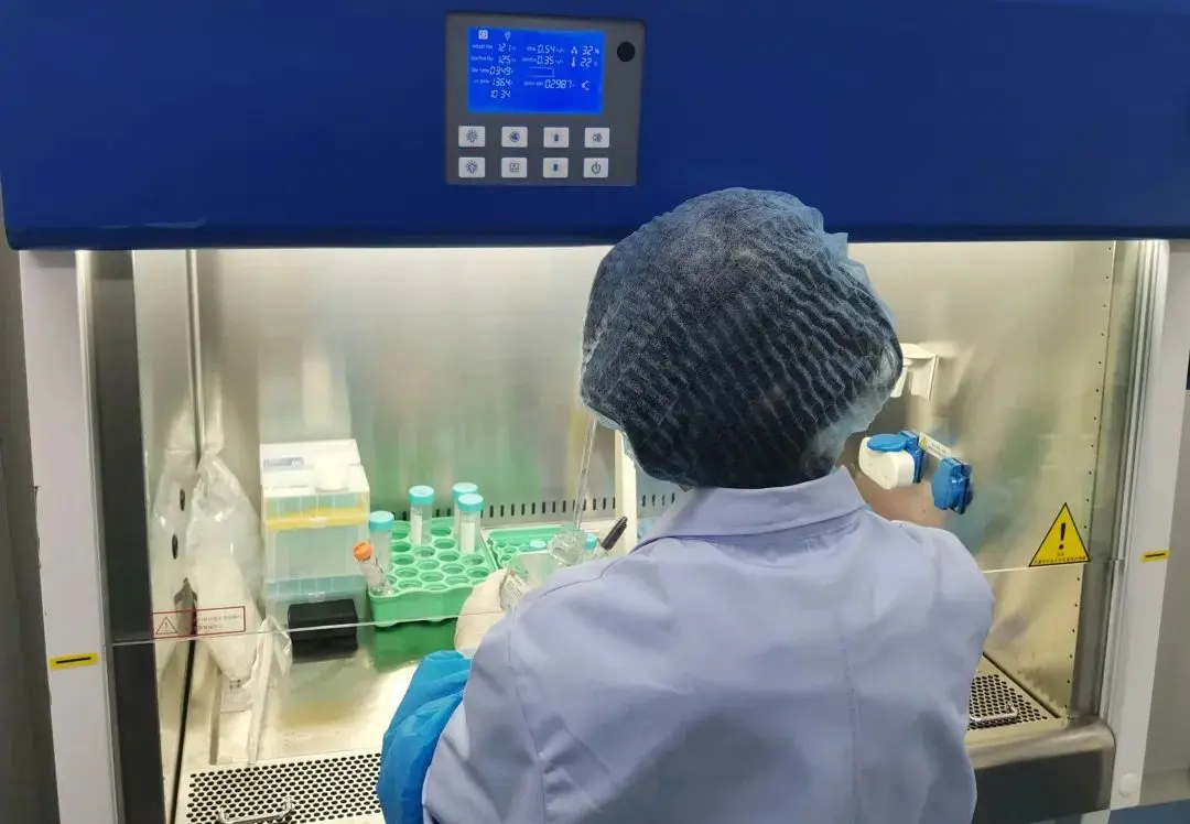 ISO 10993-23 Irritation Testing Laboratory
Leave us a message
24-hour online customer service at any time to respond, so that you worry!
