
The Basic Principle of Wireless Charging FOD
1. Introduction
FOD (Foreign Object Detection) is used in wireless charging to detect whether there is a metal foreign object between TX (transmitter) and RX (receiver) during the charging process, and to take measures to cut off the charging. During the wireless charging process, if there is a metal foreign object between TX and RX, an induced electromotive force will be generated in the alternating magnetic field, forming an induced current inside the conductor, consuming the energy output by TX and generating a large amount of heat, which will seriously affect the efficiency of wireless charging and easily cause accidents.
This article first briefly introduces the principle of FOD detection, and then uses the CPSQ8100 50W in-vehicle wireless fast charging solution launched by WPG World Peace Group as a platform to demonstrate the FOD function. CPSQ8100 is an efficient, Qi-certified magnetic induction wireless power transmitter chip designed for wireless charging systems. It supports FOD based on Q value detection and FOD based on power loss calculation. I have previously introduced this solution in detail. Friends who are interested can click on my avatar to view previous blog posts. You are also welcome to leave a message in the comment area below. I will answer any questions you have. Without further ado, let’s get to the main text!
2. FOD Detection
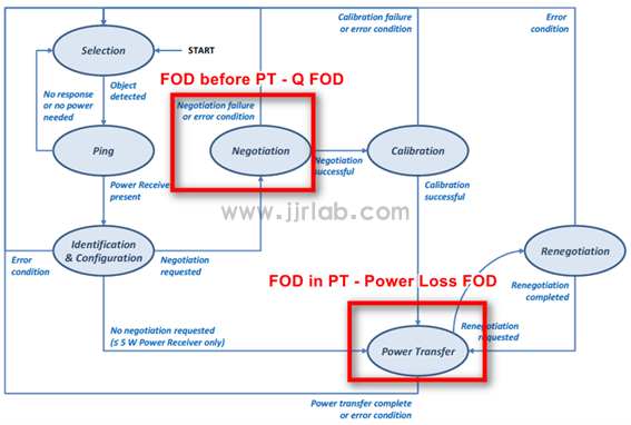
After WPC implemented the new Qi V1.2.4 certification standard in March 2018, certified products were divided into BPP (Baseline Power Profile ≤ 5W) and EPP (Extend Power Profile ≤ 15W) according to different load powers. From the perspective of system control, the power transmission from TX to RX of the EPP standard includes seven stages as shown in the figure (excerpted from WPC V1.2.4 protocol Part 1&2 - Figure 18).
FOD mainly includes two categories: QFOD (Q value detection) and Ploss FOD (Power Loss detection). We can see the communication stage in which the two mechanisms of QFOD and Ploss FOD are executed. QFOD is detected in the Nego stage, and Ploss FOD is continuously detected during power transmission.
1. Introduction to QFOD Principle
The quality factor Q can be used to indicate the size of the resonant cavity loss. When measuring the Q value, a very small amount of energy that is not enough to wake up the RX needs to be injected into the resonant cavity. At this time, a resonant current will be generated in the resonant cavity. The resonant current will decay due to the loss of energy during the resonance process. The larger the Q value, the smaller the loss of the coil, and vice versa. Then count the number of pulses CNT that meet the specified pulse width within a certain period of time, and calculate it through a specific algorithm.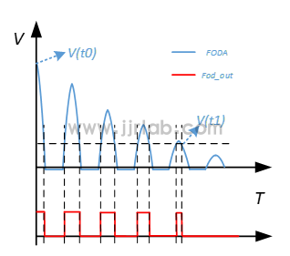
如果 TX-RX 界面存在金属异物时,谐振腔 LC 震荡的能量会被金属异物部分吸收,这导致 TX 测量得到的当前系统的 Q 值(Qm)将显著低于RX 在 Nego 阶段上报的 Q 值(Qr,这个值由测试TX 在无异物时取得),通过合适的算法可以计算得到一个恰当的阈值 Qth,当 Qm 低于 Qth 时,可以认为系统中存在异物。
Q value calculation formula: 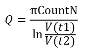
Where V(t1) is 3.3V, V(t2) is 0.2V, and CountN is the CNT value calculated by the Pulse Counter based on the LC oscillation.
In this wireless fast charging solution, Qm uses the internal Q value detection circuit of CPSQ8100 with an external full bridge, and the resonant circuit can be measured. The equivalent circuit diagram is as follows. Qr is reported by RX and obtained by demodulating the ASK data packet through the modulation and demodulation circuit.
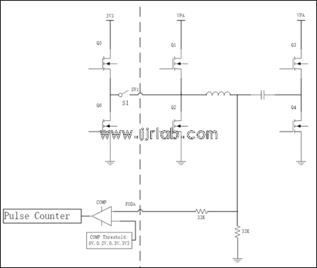
How to obtain the Qm value :
- S1, Q5, Q4 are turned on, Q1, Q2, Q3, Q6 are turned off, and the resonant capacitor is charged through the 3V inside the chip.
- S1, Q1, Q3, Q5, Q6 are turned off, Q2, Q4 are turned on, and discharge occurs through the resonant cavity (resonant capacitor and inductor).
- Using the internal detection circuit of CPSQ8100, configure the appropriate comparator reference voltage and record the number (CNT) and width (Width) of LC oscillations.
- Q value calculation.
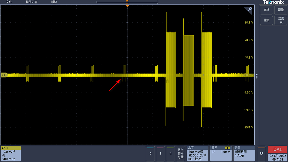
The figure above shows the waveform measured at the coil end. The arrow points to the energy that is not enough to wake up the RX mentioned above. Let's zoom in and take a look.
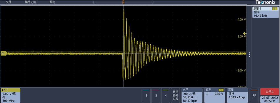
100us/div when there is no foreign matter
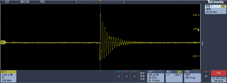
100us/div when there is foreign matter
By comparing the above figure, it can be seen that the pulse amplitude curve decays significantly faster when there is a foreign object.
2. Introduction to PLoss FOD Principle
A WPT system without any foreign matter will also have a certain amount of power loss, which includes:
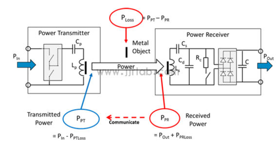
The figure below is a wireless charging power transmission model (extracted from WPC V1.2.4 protocol Part 1&2 - Figure 47). We can see that the input power of the transmitter is set to P In , which can be obtained by detecting the input voltage and input average current. The output of the rectifier bridge at the receiving end is set to P Out , which can be obtained by detecting the output voltage and output current of the rectifier bridge. If there is a metallic foreign body in the transmission magnetic field, more losses will be generated, which is set to P LOSS . The relationship between these parameters is:
TX can calculate a P Loss value through the above formula . If P Loss is greater than a certain threshold, it means that the magnetic field consumes too much energy, and then it is determined that there is a metal foreign body in the transmission magnetic field. At this time, measures such as charging interruption and alarm can be taken to avoid accidents.
3. FOD function demonstration
Below we use the 50W in-car wireless fast charging solution launched by WPG World Peace Group to demonstrate the FOD function. For the operation of the board, please refer to my other blog post "CPSQ8100 50W in-car wireless charging solution board debugging (detailed tutorial)", which will not be repeated in this article.
The test conditions are as follows:

Power on the board to ensure that the HUAWEI Mate40 Pro phone can be charged normally.
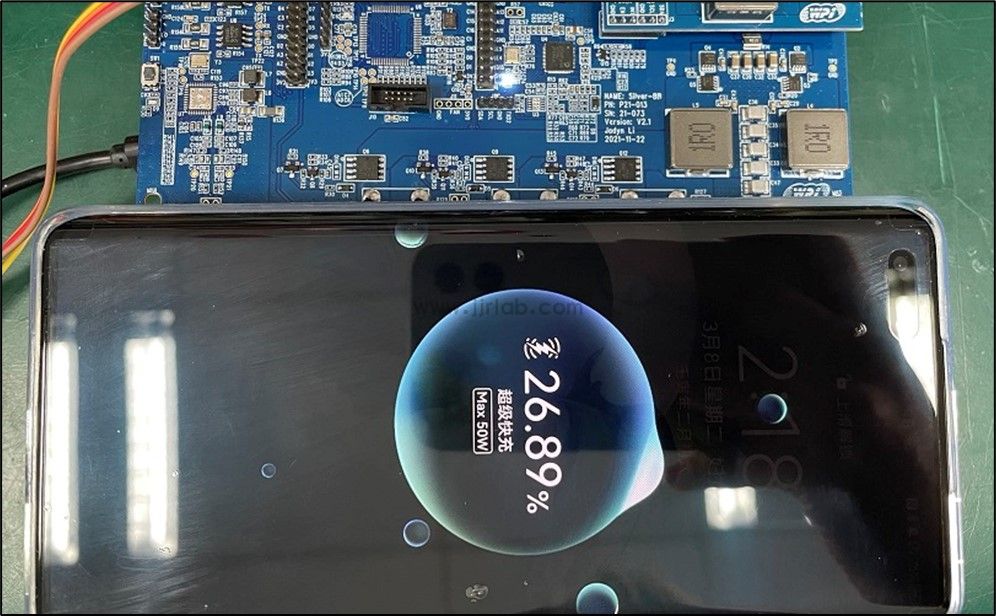
In order to test the two FOD functions separately, we temporarily turned off the Ploss FOD function on the software side when testing the QFOD function alone, and conversely, when testing the Ploss FOD, we temporarily turned off the QFOD function.
1. QFOD Function Demonstration
On the software side, turn off Ploss FOD, turn on the QFOD function separately, and use CPSGUI to read and write register values.
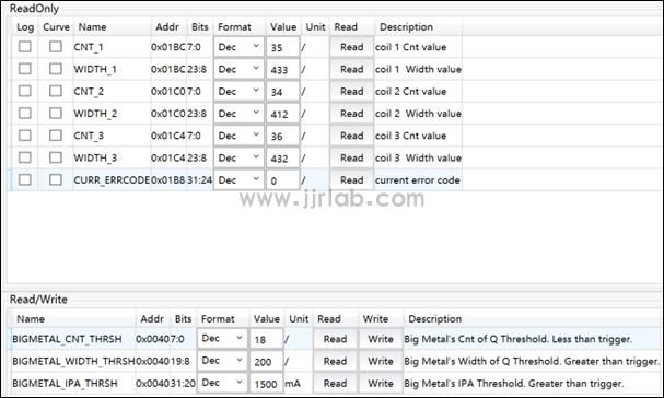
In the figure below, CNT and WIDTH represent the pulse count value and pulse width accumulated value of the energy injected into the LC resonant cavity (not enough to wake up RX) attenuated within a certain period of time. If one of them is less than the threshold set by the register, the QFOD protection is triggered. We have a three-coil solution, so it is divided into three groups of parameters. Another detection method is ping current detection. When the full bridge is turned on, if the bridge current (IPA) is greater than the threshold set by the register, the FOD protection of the coil will also be triggered.
- BIGMETAL_CNT_THRSH is the CNT threshold, currently set to 18;
- BIGMETAL_WIDTH_THRSH is the WIGTH threshold, currently set to 200;
- BIGMETAL_IPA_THRSH is the PING IPA threshold, currently set to 1500mA.
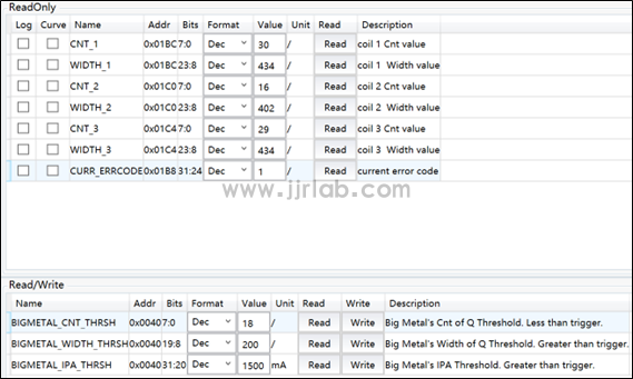
Place a coin on coil 2, and you can see the white light on the board flashing. At this time, we read CNT_2 = 16, which is lower than the BIGMETAL_CNT_THRSH threshold, and CURR_ERRCODE reports the abnormal code exp:1, triggering the QFOD protection . If you place a mobile phone on the coil, it will not start charging. We can see that coils 1 and 3 are also affected, and the specific parameters are shown in the figure below.
2. PLoss FOD Function Demonstration
Turn off QFOD on the software side and turn on the Ploss FOD function separately. This solution supports Ploss FOD functions of BPP, EPP, APPLE, SAMSUNG, HUAWEI and other types. The RX receiving end we use is HUAWEI Mate40 Pro. Take HUAWEI Ploss FOD as an example.
Use CPSGUI to read and write register values.
We need some data to fit a quadratic relationship between the ploss parameter and the power loss, and then adjust the A, B, and C parameters of the quadratic relationship according to the actual test situation to achieve the desired effect of the project. The following lists the meanings of some parameters. For specific definitions, please refer to the "Register List" and "FOD Debugging Instructions":
- Coil peak voltage = FIT_PRARM * 1000;
- Compensation parameters A, B, C (HUAWEI_PLOSS_FOD_PARAMx_A, HUAWEI_PLOSS_FOD_PARAMx_B, HUAWEI_PLOSS_FOD_PARAMx_C);
- CPloss = Ploss compensation value = (A/10^7)*coil peak voltage^2 + B*coil peak voltage + C*100;
- Ploss = PA_POWER – RP_POWER;
- PLOSS_VAL = Ploss – CPloss;
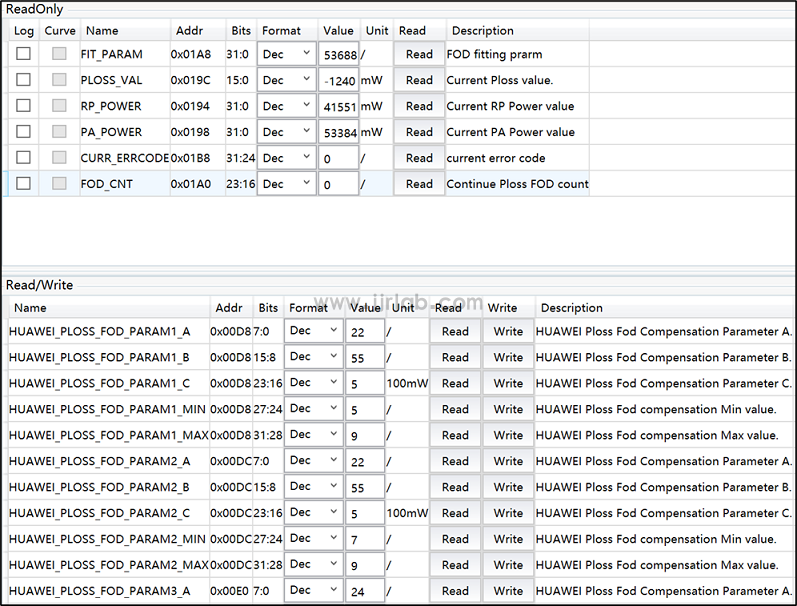
Place a coin on coil 2, then place the test device, the phone starts charging, a few seconds later you can see the white light flashing on the board, the phone stops charging. We can read that PLOSS_VAL is greater than 0 for 4 consecutive times, triggering Ploss FOD , CURR_ERRCODE reports the exception code exp:18.
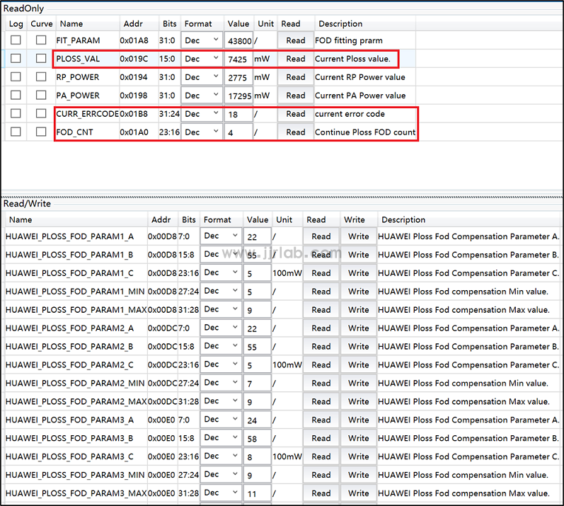
The above is the part of FOD function demonstration.You can also copy the link below, find the relevant video at the bottom of the solution introduction, and watch a more detailed solution demonstration video.
Email:hello@jjrlab.com
Write your message here and send it to us
 Toothbrush FDA Certification Testing
 Snoring Device FDA 510k Standard Testing
 Single Use Intravenous Catheter Certification Test
 Silicone Material Product Compliance Certification
 What to Do If Cytotoxicity Test Results Are Positi
 ISO 10993:5 Cytotoxicity Testing Methods
 FDA ISO 10993-1 Biocompatibility Evaluation Guidel
 In Vitro Cytotoxicity Testing for Medical Devices
Leave us a message
24-hour online customer service at any time to respond, so that you worry!


