
Multimedia equipment EMC EN 55032 testing
EN 55032 test requirements in EMC
1 Introduction
EMC is mainly divided into 2 parts:
1. EMI : The interference caused by the product itself to the outside world.
2. EMS : interference caused by external factors to the product.
EN 55032: Emission requirements for multimedia products in electromagnetic compatibility (EMC) . That is, the testing requirements for EMI .
EN 55035: Immunity requirements for multimedia products in electromagnetic compatibility (EMC) . That is, the testing requirements for EMS .
2. Standard distinction
Different countries and regions have different standards and certification requirements for multimedia products. Some countries require EMI+EMS certification, while some countries only require EMI certification. Here are some commonly seen standards:
2.1 , EN 55032 and EN 55035 : Mainly for the requirements of the EU region, some non-EU countries will also use this standard directly.
2.2 , CISPR 32 and CISPR 35 : Mainly used by some Middle Eastern countries, South Korea ( converted to KC) and Australia, and some African countries will also use this standard.
2.3 , GB9254 , GB13837 and GB/T17618 , GB/T9383 : used for domestic certification in China.
2.4 , J55032 : used in Japan. Multimedia products only need to undergo EMI testing and certification.
2.6 , fcc part 15B : American standard. Multimedia products only need to undergo EMI testing and certification.
2.7 , ICES-003 : Canadian standard. Multimedia products only need to undergo EMI testing and certification.
3. Product classification
3.1 . Distinguished by use environment ( related to test limits and levels ) :
1 ) Class B : For use in residential environments.
2 ) Class A : Products other than Class B are classified as Class A.
3.2 . Distinguished by differential mode / common mode ( related to test requirements ) :
1 ) Differential mode: between 2 signal lines ( without ground wire ) . It can be roughly understood as a product with only LN .
2 ) Common mode: 2 signal lines and ground (GND) . It can be roughly understood as a product with only LN-GND .
4. Ports of multimedia products
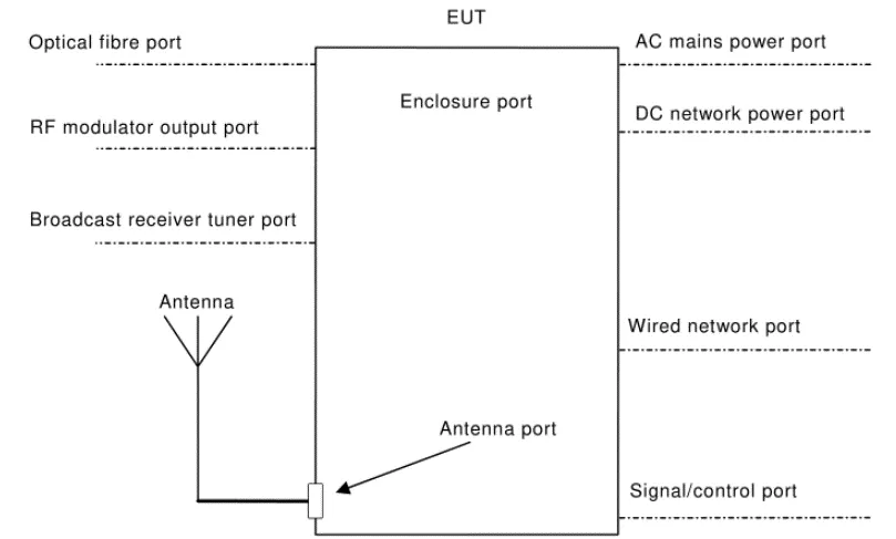
4.1 . AC power port: the port connected to the mains power network.
Note 1 : Equipment with a DC power port and powered by a dedicated AC/DC power converter is defined as AC mains equipment.
4.2 . DC network power port: A DC power port that is powered by a non-dedicated AC/DC power converter connected to the DC power supply network and does not support communication.
Note 1 : Equipment with a DC power port powered by a dedicated AC/DC power converter is considered an AC mains equipment.
Note 2 : DC power ports that support communications are considered wired network ports, such as Ethernet ports including Power over Ethernet (POE) .
4.3 . Wired network port: used to connect voice, data and signal transmission, designed to interconnect widely dispersed systems by directly connecting to single-user or multi-user communication networks.
Note 1: These examples include CATV , PSTN , ISDN , xDSL , LAN and similar networks.
NOTE 2: These ports may support shielded or unshielded cables and may carry AC or DC power if this is part of the telecommunications specification.
4.4 . Signal / control port: used for interconnection between EUT components or between EUT and local AE , and used in accordance with relevant functional specifications ( such as the maximum length of the cable connected to it ) .
Note 1: Examples include RS-232 , Universal Serial Bus (USB) , High Definition Multimedia Interface (HDMI) .
4.5 . Optical fiber interface: the port where optical fiber is connected to the device.
4.6 . RF Modulation Output Port: A port intended to be connected to the broadcast receiver tuner port in order to send signals to the broadcast receiver.
4.7 . Broadcast receiver tuner port: A port used to receive modulated RF signals with terrestrial, satellite and / or cable transmission of audio and / or video broadcasts and similar services .
Note 1: This port can be connected to an antenna, cable distribution system, video recorder or similar device.
4.8 . Shell port: the physical boundary where electromagnetic fields can radiate. Product casing.
4.9 . Antenna port: used to connect antennas used to intentionally transmit and / or receive radiated radio frequency energy.
5. EMI part test requirements
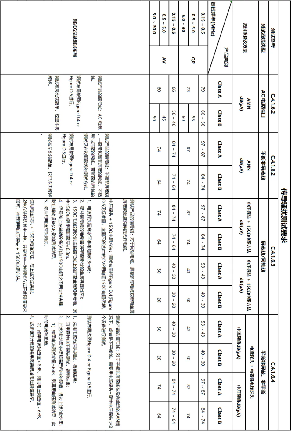
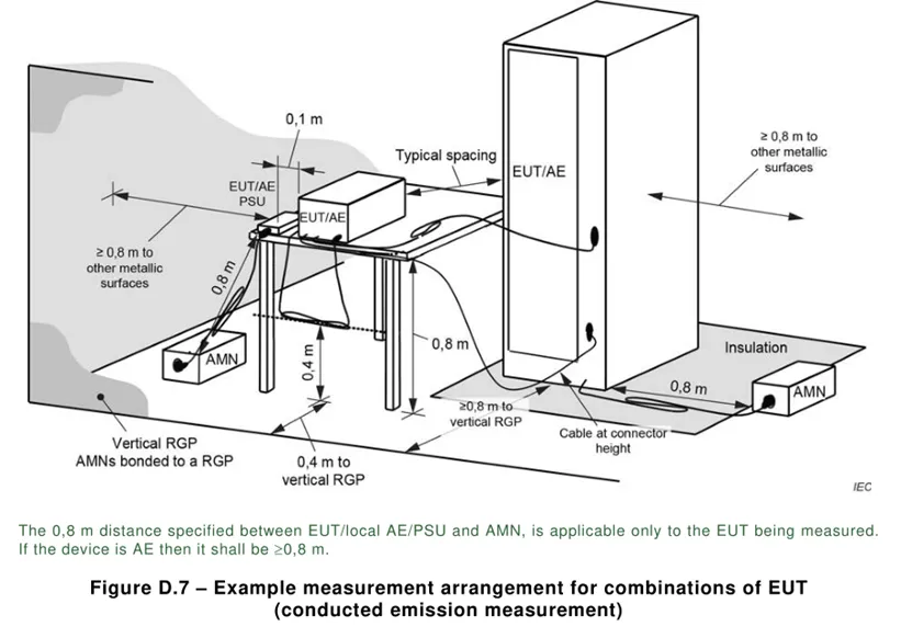
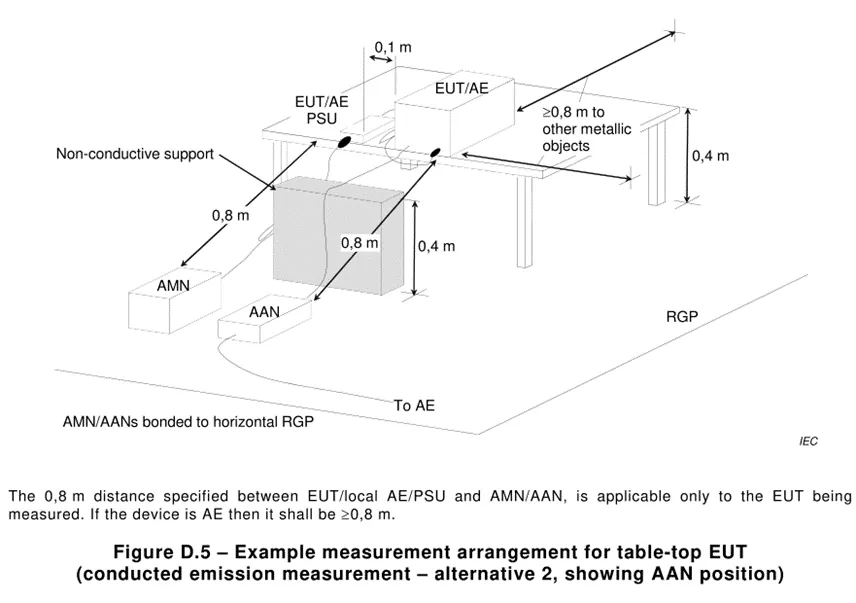
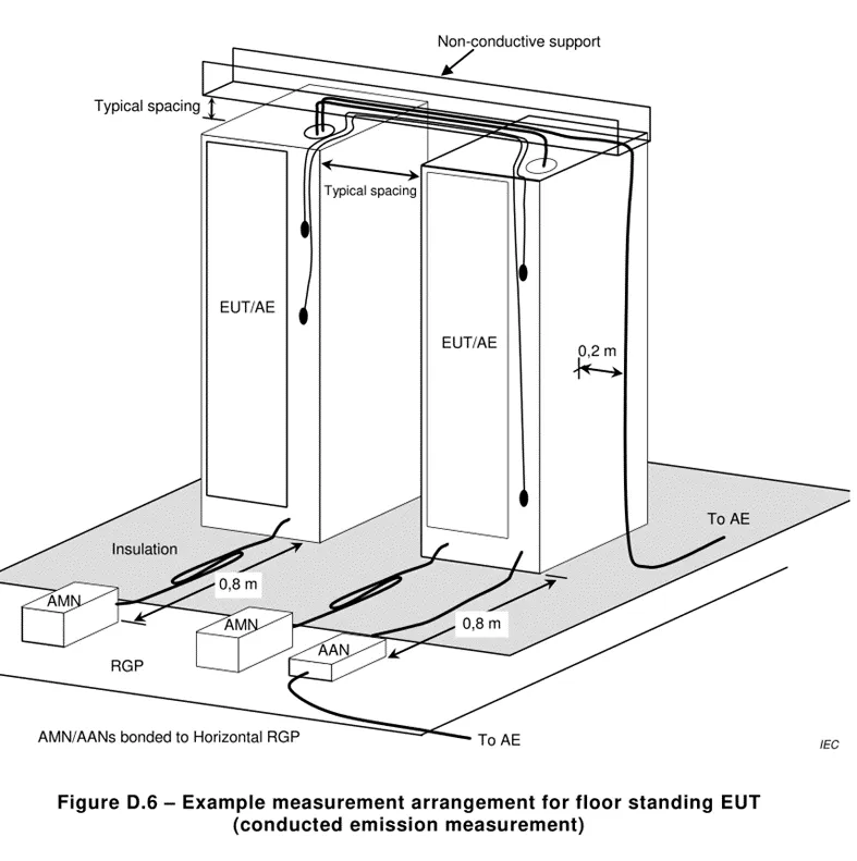
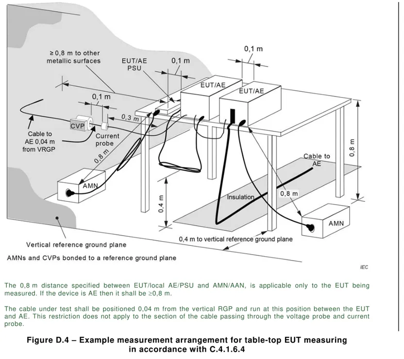
5.1 . Conducted emission harassment: Harassment at the frequency of 0.15k~30MHz is mainly transmitted through cables, so conduct harassment tests on cables. This test generally tests the AC power port and signal / control lines. Other optical fibers, RF modulation output terminals, broadcast receiver tuners and antenna ports are not described for the time being. The text seems boring, so here are the tables and layout diagrams.
5.2 . Radiated emission harassment: Harassment above the 30MHz frequency band mainly propagates through space, so an antenna must be used for space radiation harassment testing.
1) Depending on the main operating frequency of different products, the frequency bands required for testing are also different, see the table below:
The highest frequency required for radiation disturbance testing | |
Highest operating frequency (Fx) | highest test frequency |
Fx ≤ 108 MHz | 1 GHz |
108 MHz < Fx ≤ 500 MHz | 2 GHz |
500 MHz < Fx ≤ 1 GHz | 5 GHz |
Fx > 1 GHz | 5*Fx up to 6 GHz |
Note 1: For FM and television broadcast receivers, F is determined by the highest frequency generated or used, excluding the local oscillator and tuning frequency. | |
Note 3: For outdoor units of home satellite reception systems, the maximum measurement frequency should be 18 GHz . | |
Note 3: If Fx is unknown, test up to 6 GHz . | |
2 ) Radiation test site
Test site type | Limitations and Definitions |
Semi-anechoic chamber (SAC) , semi-open space ( OATS, with weatherproof cover) | The maximum width of products and auxiliary equipment must be within the NSA range of the test site, NSA ; generally only used for space radiation testing below 1GHz . |
Open test site ( OATS, without weatherproof cover) | Same as above. |
Free Space Open Test Site (FSOATS) | It is used as a test site for 1GHz frequency, that is, it is covered with absorbing materials on the basis of SAC and OATS ; or equivalent to FAR . |
Fully Anechoic Chamber (FAR) | Covered with absorbing materials, it is used as a 1GHz space radiation test site. |
3 ) Radiation disturbance limits
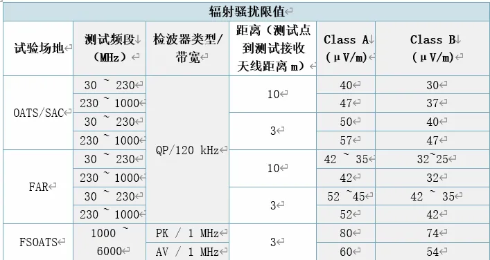
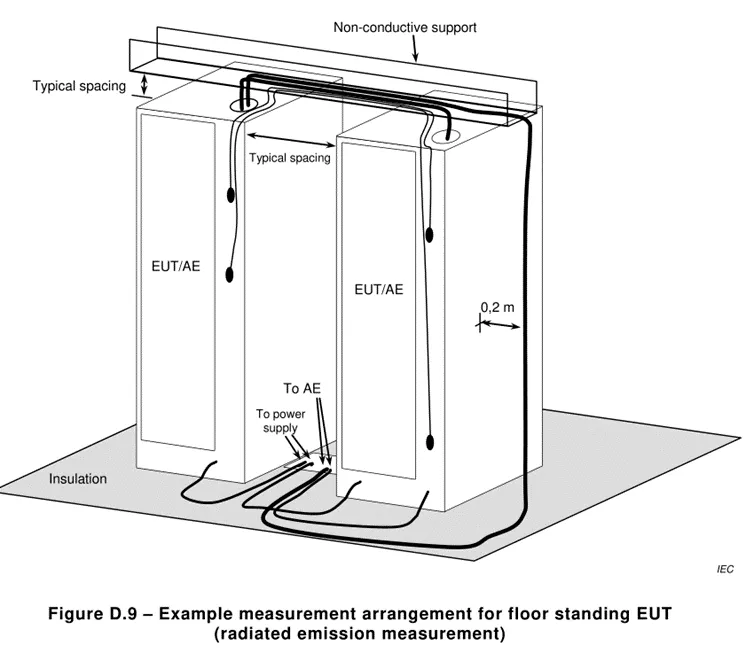
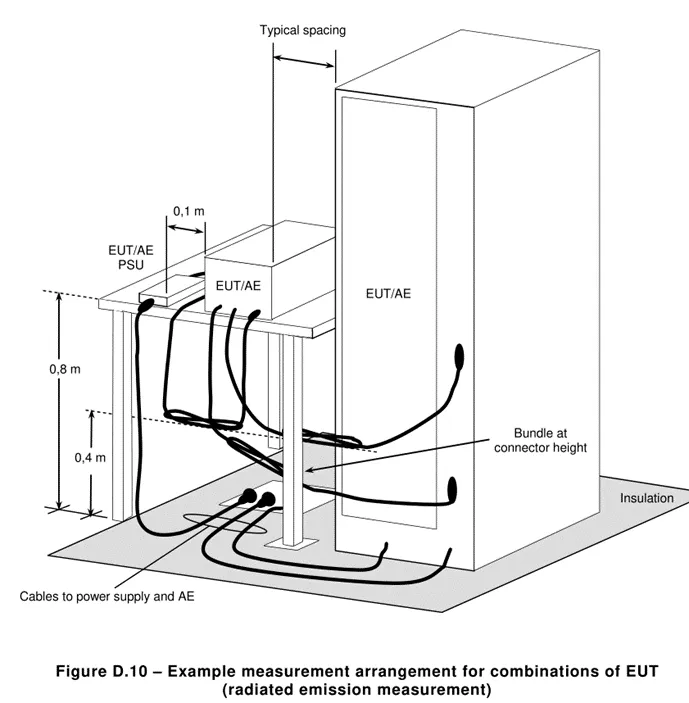
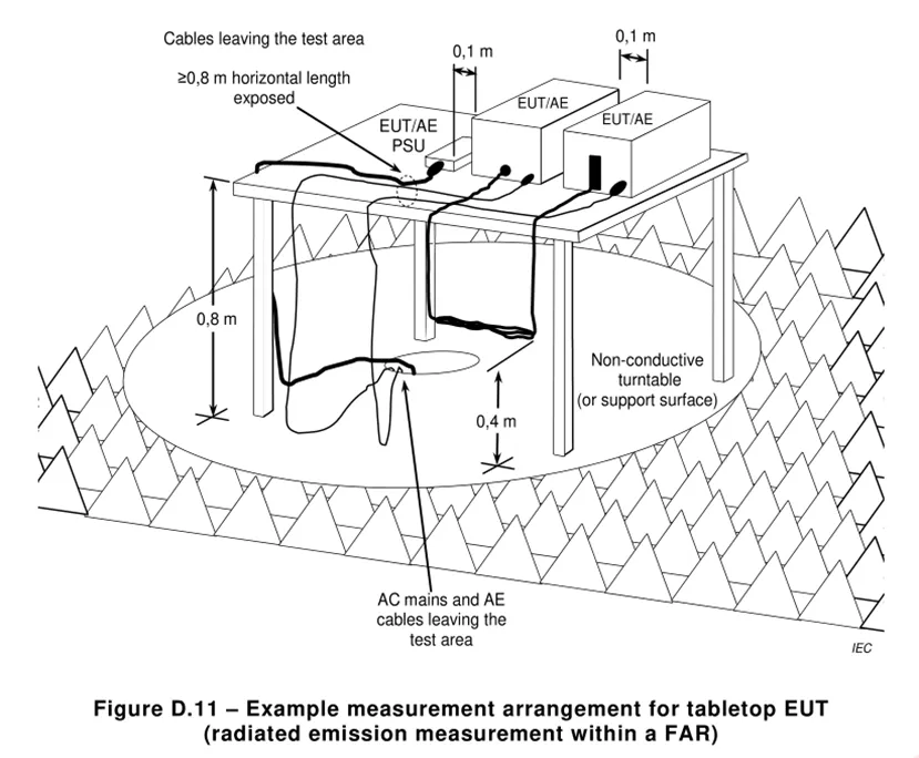
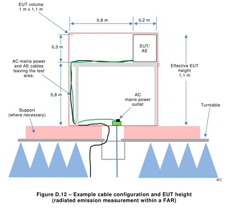
5.2.1 Radiated disturbance test layout
Email:hello@jjrlab.com
Write your message here and send it to us
 IECEE CBTL Testing Laboratory for IVD Medical Devi
 China OECD GLP-Certified Laboratory
 Packaging Validation ISO 11607 Test Report
 What is the ISO 11607-1 Packaging Validation Test?
 How to get an ISO 11737-1 Test Report?
 Orthopedic Implant Cleanliness Testing
 What is ISO 10993-23:2021 Irritation Testing?
 ISO 10993-23 Irritation Testing Laboratory
Leave us a message
24-hour online customer service at any time to respond, so that you worry!
