
Electronics CE EMC Testing and Certification
What is emc certification?
EMC stands for Electromagnetic Compatibility. It refers to the ability of a device or system to operate in its electromagnetic environment without causing intolerable electromagnetic interference (EMI) to other devices or systems. EMC baseline testing is a preliminary test conducted early in product development, aimed at assessing the product's basic performance in an electromagnetic environment, identifying potential electromagnetic interference issues, and taking corrective actions in advance. This test helps ensure that the product can pass the final conformity test and be launched on time. Therefore, EMC includes two main aspects:
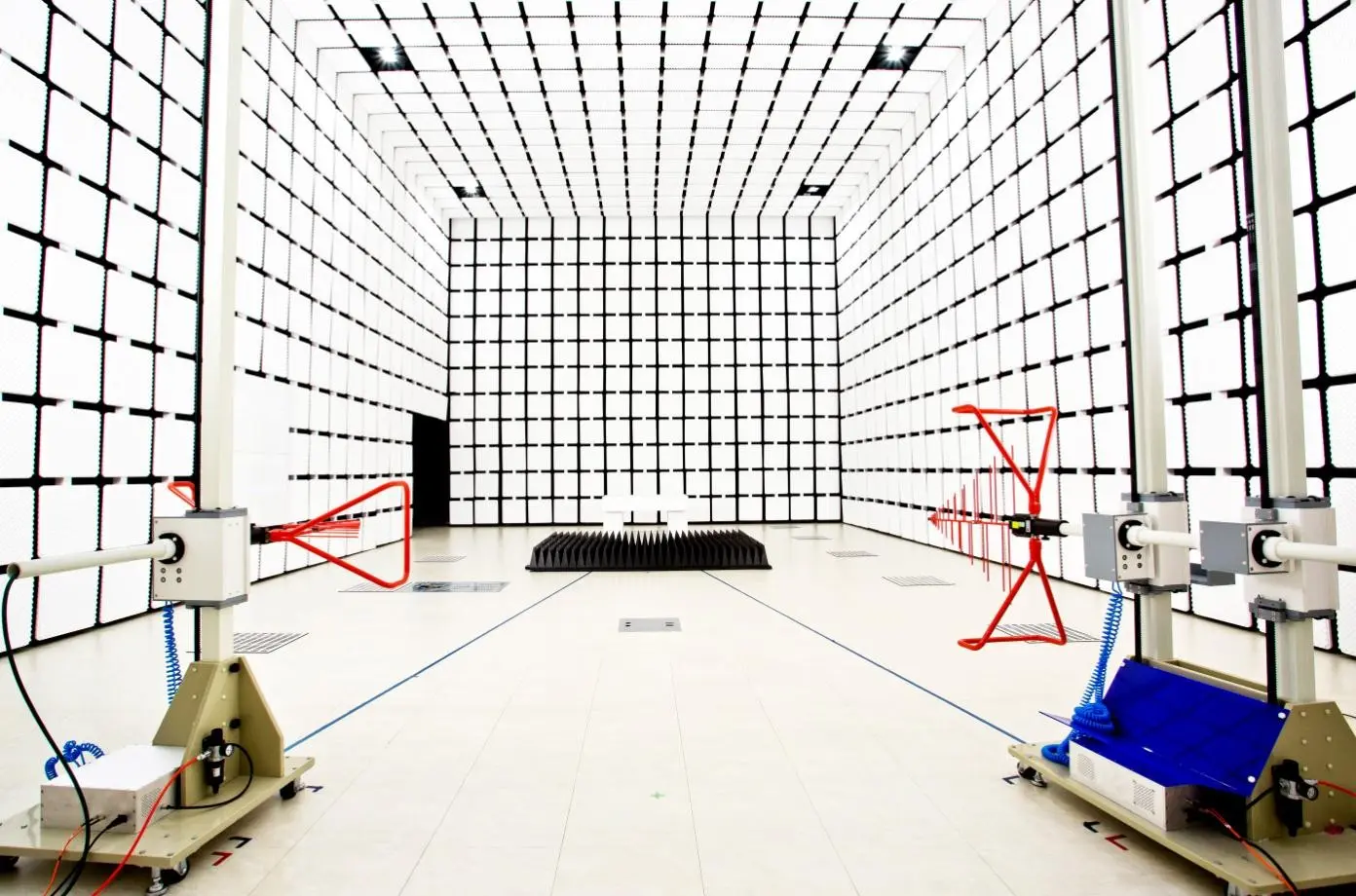
1. Control of Electromagnetic Interference (EMI) Emissions: The electromagnetic interference (i.e., electromagnetic radiation) generated by the device during normal operation must be below a certain limit to avoid interference with other devices or systems. This involves using techniques like internal circuit layout, filtering, and shielding to reduce unnecessary electromagnetic radiation.
2. Ensuring Electromagnetic Susceptibility (EMS): The device should have a certain level of resistance to electromagnetic interference, meaning it should be able to operate normally in a specific electromagnetic environment without malfunction or performance degradation due to external EMI. This requires the device to consider electromagnetic compatibility during the design phase and adopt appropriate protection measures to improve its immunity to interference.
EMC Testing Items
1. RF Radiation Immunity
RF Radiation Immunity: Simulate an electromagnetic radiation environment with a certain intensity to assess the RF radiation immunity of civilian equipment. Test the ability of the device to resist electromagnetic radiation interference.
2. Electrostatic Discharge Immunity
Electrostatic Discharge Immunity: Large static charges can generate high voltage (several thousand to tens of thousands of volts), which can easily damage internal circuits of electronic products. Test the device's ability to withstand electrostatic discharge interference.
3. Electrical Fast Transient/Burst Immunity
Electrical Fast Transient/Burst Immunity: Verify the device's immunity to transient disturbances generated by switching processes such as inductive load relay contact bounce. Test the device’s ability to resist pulse interference signals.
4. Surge Immunity
Surge Immunity: Transients from power system switching or lightning can cause rapid changes in voltage and current, resulting in overvoltage and overcurrent that may damage the product. Test the device’s ability to resist surge current impact.
5. RF Conducted Immunity
RF Conducted Immunity: Low-frequency cables are more likely to act as antennas and pick up electromagnetic fields. Therefore, low-frequency conducted immunity testing is used to evaluate the device's ability to resist electromagnetic interference signals through conductors.
6. Power Frequency Magnetic Field Immunity
Power Frequency Magnetic Field Immunity: Power frequency magnetic fields generated by currents in conductors or other nearby equipment (e.g., transformer leakage flux) can affect the reliable operation of electronic devices or systems.
7. Impulse Magnetic Field Test
Impulse Magnetic Field Test: Low, medium, and high-voltage power system faults can generate impulse magnetic fields, affecting the reliability of electronic devices and systems.
8. Damped Oscillatory Magnetic Field
Damped Oscillatory Magnetic Field: Damped oscillatory magnetic fields are generated when high-voltage circuit breakers open, potentially affecting the reliable operation of electronic devices and systems.
9. Voltage Dip Immunity
Voltage Dip Immunity: Voltage sags, short interruptions, or large changes in load can cause voltage dips in low-voltage networks, which may lead to malfunctions in the device.
10. Ring Wave Immunity Test
Ring Wave Immunity Test: Ring waves are transient oscillations caused by lightning strikes or power load switching. This test evaluates the device’s immunity to these transient waves.
11. Damped Oscillatory Wave Immunity
Damped Oscillatory Wave Immunity: These are pulse groups of damped oscillations caused by switching operations in power plants and heavy industrial equipment. It is used to assess the device’s tolerance to these oscillations.
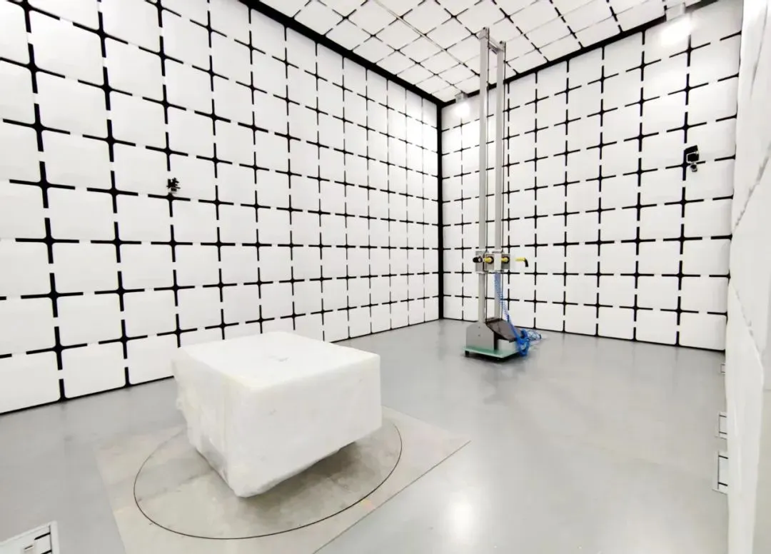
12. Radiated Emissions Test
Radiated Emissions Test: Measures the radiated interference from electronic or electrical devices/systems during normal operation. This includes electromagnetic emissions from sources or interfaces, measuring radiation outside the working frequency.
13. Conducted Emissions Test
Conducted Emissions Test: Refers to electromagnetic interference caused by voltage or current traveling through signal cables, power lines, or ground lines from inside the system. This is also known as interference voltage testing.
14. Harmonic Current Test
Harmonic Current Test: When the input load is a nonlinear circuit, it distorts the input current, which is no longer a sine wave. These harmonic currents decrease the efficiency of power supplies and pollute the grid.
15. Voltage Dip Test
Voltage Dip Test: Voltage dips and short interruptions occur due to network faults or large load changes. Voltage fluctuations can cause failures if the EUT (Equipment Under Test) does not react timely to power supply changes.
16. Voltage Flicker Test
Voltage Flicker Test: This ensures the product does not cause excessive flicker in connected lighting equipment.
EMC Testing Report
To obtain an EMC test report, products need to be tested in a professional EMC testing laboratory. After testing, the laboratory will issue a report based on the test results. The general steps for obtaining an EMC report are as follows:
1. Choose a Testing Laboratory: Select a qualified EMC testing laboratory with appropriate experience.
2. Submit Products and Documents: Provide the products and any necessary technical documentation to the laboratory.
3. Perform Tests: The laboratory will conduct EMC tests based on product type and applicable standards.
4. Analyze Results: After testing, the laboratory will analyze the results and determine if the product complies with all relevant EMC standards.
5. Issue Report: If the product passes the tests, the laboratory will issue an EMC test report. If the product fails, the laboratory may provide detailed data and corrective recommendations.
6. Obtain Report: The report will typically be provided to the client in paper or electronic form.
7. Verify Report: In some cases, the report number can be verified through official platforms, such as the National Certification and Accreditation Information Public Service Platform in China.
How Much Does emc testing cost?
The cost of EMC testing varies depending on the test items, testing environment, equipment, and laboratory. Please contact us for more information.
EMC Testing Standards (Partial)
1. Information Technology Equipment
CISPR 22, CISPR 32, EN 55032, AS/NZS CISPR 22, VCCI V-3, J55022, fcc part 15, ICES-003, GB 9254
2. Audio/Video/Broadcasting Products
CISPR 13, CISPR 32, EN 55032, AS/NZS CISPR 13, J55013, GB 13837
3. Household Appliances, Power Tools, and Similar Equipment
CISPR 14-1, EN 55014-1, AS/NZS CISPR 14. 1, J55014-1, GB 4343. 1
4. Electrical Lighting and Similar Equipment
CISPR 15, EN 55015, AS/NZS CISPR 15, J55015, fcc part 18, ICES-005
5. Industrial, Medical, and Scientific Products
CISPR 11, EN 55011, AS/NZS CISPR 11, FCC PART 18, ICES-001
6. Medical Electrical Equipment
IEC/EN 61326, GB/T 18268
7. Residential, Commercial, and Light Industrial Products
IEC/EN 61000-6-3, GB/T 17799. 3
8. Industrial Environment Products
IEC/EN 61000-6-4, GB/T 17799. 4
9. Electrical Equipment for Measurement, Control, and Laboratory Use
IEC/EN 61326-1, GB/T 18268. 1
10. Harmonic Current & Voltage Flicker
IEC/EN 61000-3-2, GB 17625. 1, IEC/EN 61000-3-3
11. Uninterruptible Power Supply Equipment (UPS)
IEC/EN 62040-2
12. Other
EN 50130-4, EN 50121-3-2, EN 50412-2-1
Electromagnetic Interference Sources
Electromagnetic interference sources include power switches, radio transmitters, lightning, and interference generated by electronic equipment. Power switches are common sources of EMI, as they can produce harmonic currents and voltage fluctuations that may interfere with other devices.
Electromagnetic Shielding and Filtering Technology
Electromagnetic shielding and filtering techniques are widely used in electronic devices to meet EMC requirements. Shielding isolates the interference source using metal materials, while filtering blocks or attenuates the interference signal through specially designed circuits or devices.
EMC Certification Requirements in Different Countries
- Europe CE-EMC Certification: Directive 2014/30/EU, including both EMI and EMS parts.
- USA FCC Certification: Primarily tests the EMI part, no EMS requirements.
- Canada ic certification: Covers emi testing for wired and wireless products.
- China 3c certification: Follows national standards for EMI and EMS.
- Japan pse certification: Includes EMC requirements for certain electrical products.
- South Korea kc certification: Requires both safety and EMC certification.
- Australia C-Tick (RCM) Certification: Combines safety and EMC requirements.
Design Strategies for Improving Electromagnetic Compatibility
In the design phase, strategies such as proper circuit board layout, appropriate filtering components, shielding materials, and signal integrity considerations are essential for improving electromagnetic compatibility.
EMC Testing Instrument Selection
- CE (Conducted Interference): Choose appropriate equipment based on EUT type and applicable standards.
- DP (Radiated Power): Focus on measuring radiated interference.
- RS (Radiated Susceptibility): Requires specific equipment for immunity testing.
EMC testing has become an essential quality indicator for electronic and electrical products. With technological advancements, the importance of addressing EMC issues will continue to grow, requiring ongoing exploration of new methods and solutions.
Email:hello@jjrlab.com
Write your message here and send it to us
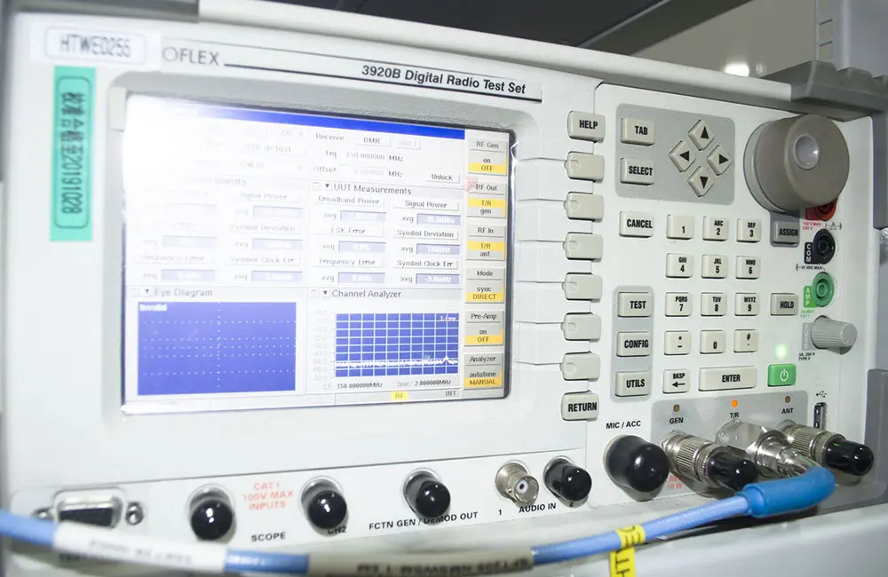 LED Lighting EMC Testing Service
 EU REACH Compliance Testing Services
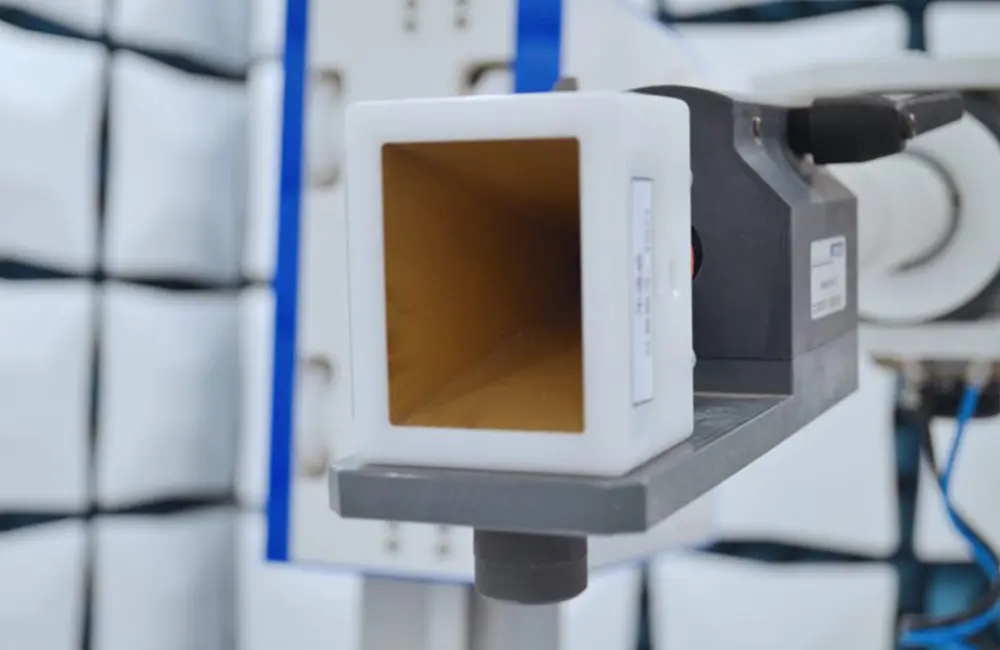 Electronic and Electrical Reliability Testing Serv
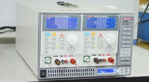 Electronic & Electrical Safety Compliance Test
 Shenzhen Electronic Electromagnetic Compatibility
 How to Test IP68 Rating
 Differences Between FDA and LFGB for Food Contact
 Process and Precautions for Amazon CPC Certificate
Leave us a message
24-hour online customer service at any time to respond, so that you worry!
