
Amazon Wireless FCC-ID Certification Testing
Amazon Wireless FCC-ID Certification Testing Items and Steps. In recent years, a significant portion of products exported from China to the United States are communication electronic products. According to the relevant sections of the U.S. Federal Communications Regulations (CFR Title 47), all communication electronic products entering the U.S. must undergo FCC certification. This involves testing and approval by laboratories authorized by the FCC, based on FCC technical standards.
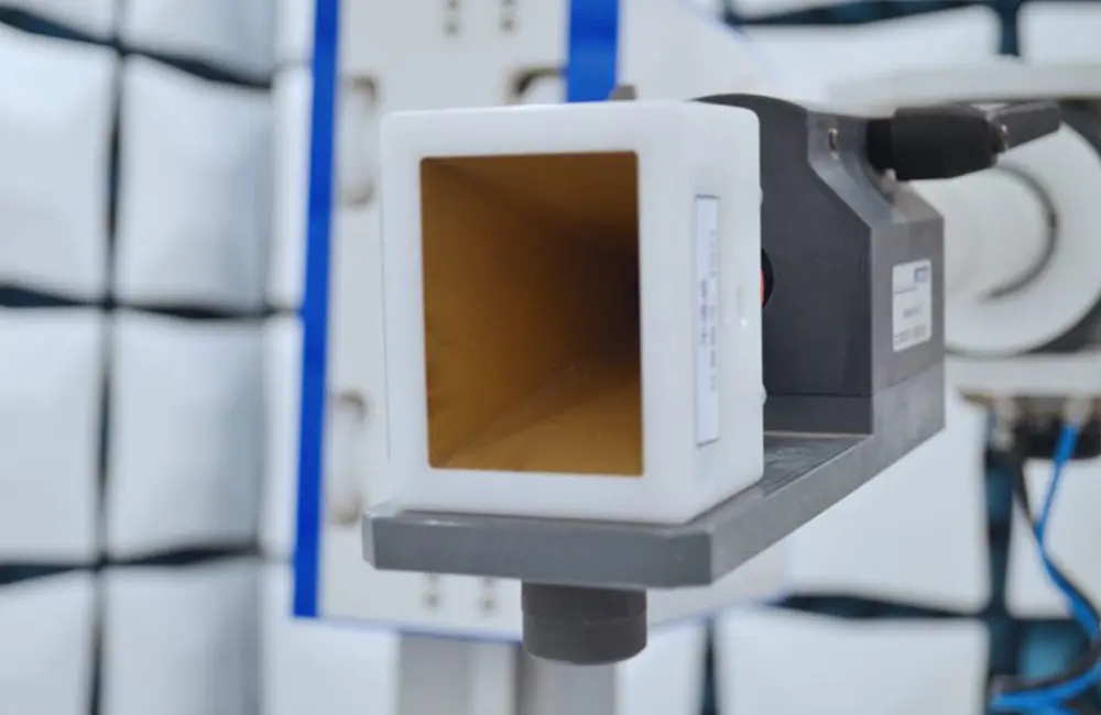
FCC-ID Test Report Overview:
FCC stands for the Federal Communications Commission, which directly reports to Congress. It coordinates domestic and international communications by controlling radio broadcasting, television, telecommunications, satellite, and cable. It is responsible for authorizing and managing radio frequency transmission devices and equipment, excluding federal government usage. According to the U.S. Federal Communications Regulations (CFR47), all electronic products entering the U.S. must undergo electromagnetic compatibility certification (FCC certification).
FCC-ID: This is a CERTIFICATION certificate for FCC-ID certification. It applies to low-power emitters such as cordless phones, remote controls for automatic doors, remote-controlled toys, security alarm systems, devices emitting radio frequency energy intentionally under Part 15, industrial, scientific, and medical devices for consumer use under Part 18, automatic frequency receivers, super regenerative receivers, TV interface devices, as well as personal computers and peripherals. The product must be tested in an FCC-approved testing facility, and after obtaining the test report, technical materials, including product detail photos, block diagrams, user manuals, etc., must be submitted to the FCC Tcb testing room. The FCC TCB testing room will confirm the accuracy of the materials and issue a certificate, granting an fcc id number.
Radio Equipment FCC-ID Certification Testing Items:
1. Output Power:
According to the power adjustment procedure, adjust the voltage and current values fed into the RF amplifier circuit to its maximum rated power emission state, and apply an appropriate load to the RF output port to test the maximum RF output power. For different emission types, the method of power adjustment will vary, and this should be detailed in the test report.
2. Modulation Characteristics:
1) For communication products with voice modulation, measure the frequency response curve of the audio modulation circuit in the 100-5000Hz range. If the product uses an audio low-pass filter, measure the frequency response curve of the audio filter.
2) For products with modulation limiting processing, measure the relationship curve between modulation percentage and input voltage across the entire modulation frequency and signal power level range.
3) For wireless telephone transmitters using peak envelope power limiting circuits such as single-sideband or independent sideband, measure the relationship curve between peak envelope output power and input voltage.
4) Other types of products will be processed according to the certification type and corresponding regulations.
Following the power adjustment procedure, adjust the voltage and current values fed into the RF amplifier circuit to its maximum rated power emission state, and apply an appropriate load to the RF output port to test the maximum RF output power. The power adjustment method will vary for different emission types and should be explained in the test report.
3. Occupied Bandwidth:
When measuring occupied bandwidth, the measurement method will vary depending on the modulation type, but the basic principle is to test under typical service conditions where the modulation signal has the highest amplitude. Detailed descriptions of the input modulation signal should be provided in the report.
4. Spurious Emissions at Antenna Port:
In addition to the useful RF power or voltage at the product’s frequency point, spurious frequencies also need to be measured. During measurement, an appropriate dummy antenna can be attached to the antenna output port. Harmonics and notable spurious emission points should be closely monitored.
5. Spurious Radiated Field Strength:
This test primarily detects the field strength of harmonics and significant spurious emission points at the product's housing port, control circuit module, and power ports. Products with operating frequencies below 890 MHz must be measured in an open field or anechoic chamber. On-site measurements should involve detailed investigation and analysis of nearby RF sources and significant reflective objects.
6. Frequency Stability:
Frequency stability tests include examining how frequency stability changes with environmental temperature and input voltage variations. In special cases, the test may also involve checking frequency stability when the product is paired with different antennas or when it is near large metallic objects.
Wireless Device FCC-ID Certification Process:
1. The client submits an application form (a blank form is provided by China JJR Laboratory).
2. The client signs a testing contract with our company.
3. Sample testing is conducted, and materials such as electrical schematics, external/internal photos, oscillator circuit block diagrams, user manuals, nameplate markings, operational principles, etc., are prepared (depending on the product).
4. After successful testing, if it's FCC VOC certification, our company directly issues a certificate and report. If it's FCC DOC or ID certification, our company will submit the application materials.
5. Once the enterprise obtains FCC certification, the fcc logo can be used on the product.
Email:hello@jjrlab.com
Write your message here and send it to us
 Toothbrush FDA Certification Testing
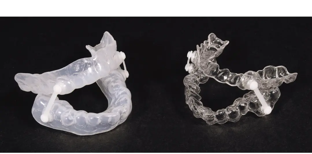 Snoring Device FDA 510k Standard Testing
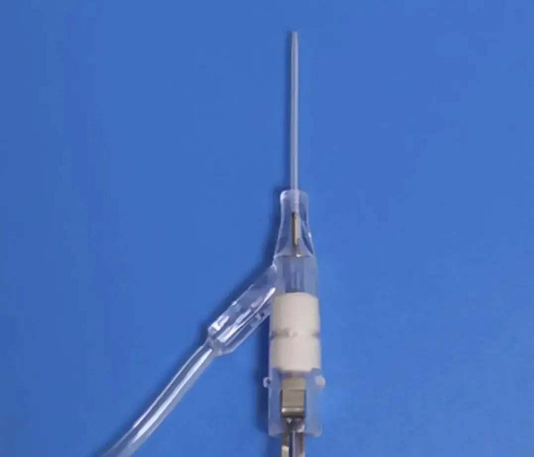 Single Use Intravenous Catheter Certification Test
 Silicone Material Product Compliance Certification
 What to Do If Cytotoxicity Test Results Are Positi
 ISO 10993:5 Cytotoxicity Testing Methods
 FDA ISO 10993-1 Biocompatibility Evaluation Guidel
 In Vitro Cytotoxicity Testing for Medical Devices
Leave us a message
24-hour online customer service at any time to respond, so that you worry!
